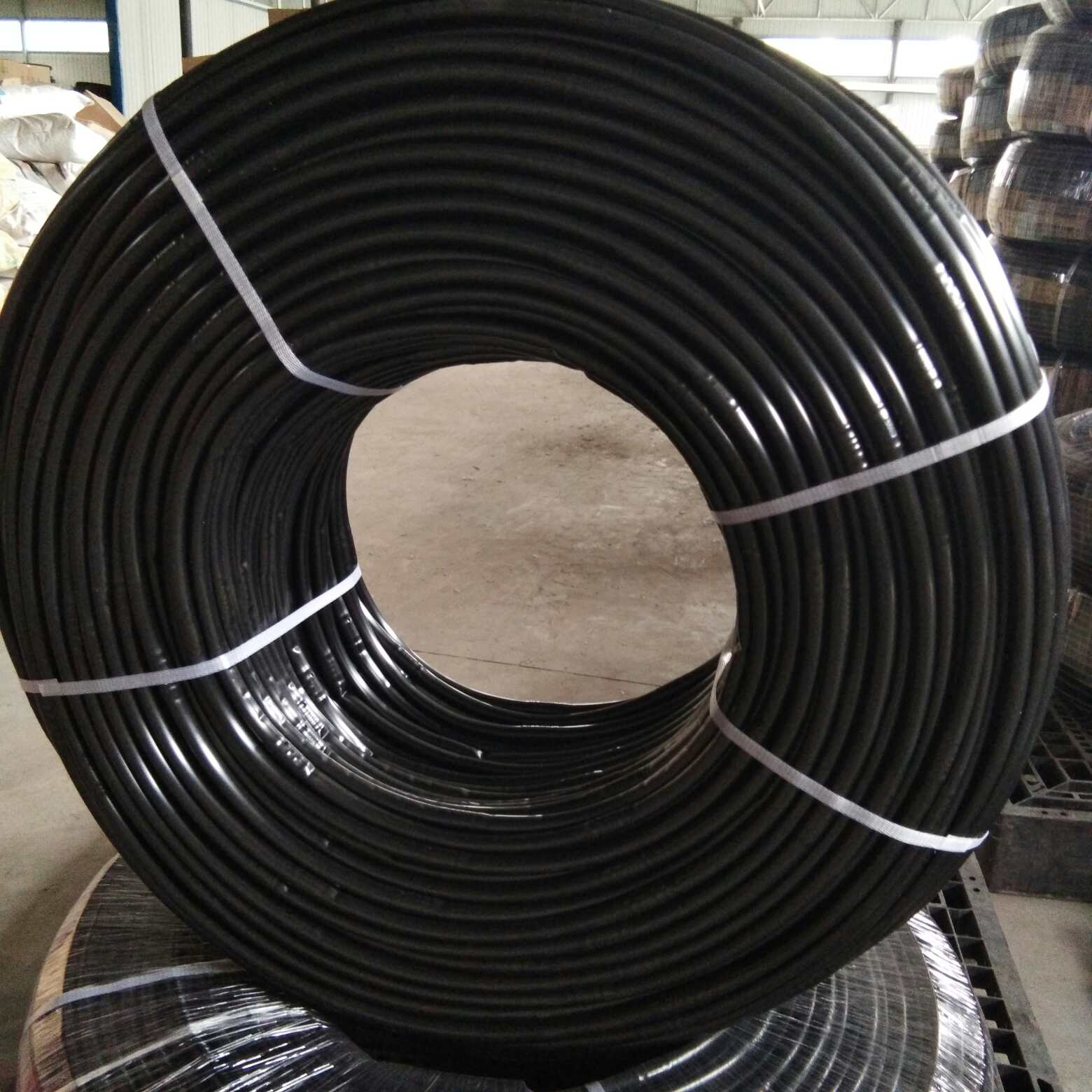
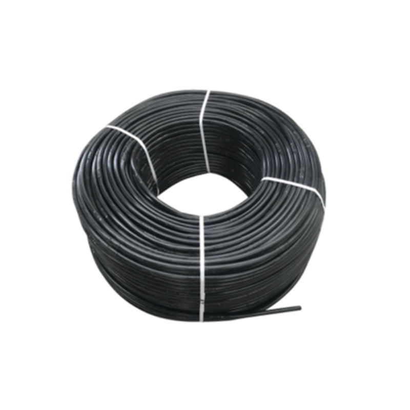
The installation and integration of a 12mm dripline into an irrigation system involve several steps to ensure precise and efficient water distribution to plants.
Here’s a general guideline on how to install and incorporate a 12mm dripline:
Materials Needed:
- 12mm dripline
- Mainline tubing (commonly made of PVC or polyethylene)
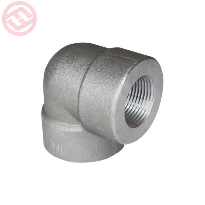
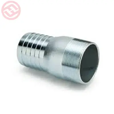
- Fittings (such as connectors and adapters)
- Filter (to prevent clogging)
- Pressure regulator (if required)
- Stake or holder (to secure the dripline)
- Hole punch tool (if not using pre-punched dripline)
Installation Steps:
- Design Your Layout: Plan the layout of your irrigation system, considering the placement of plants, soil type, and water requirements. Determine the mainline’s path and where the dripline will be installed.
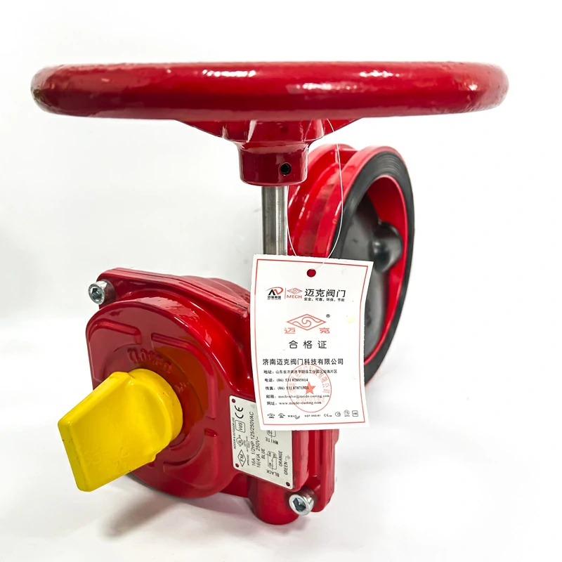
- Prepare the Mainline: Cut the mainline tubing to the desired lengths, if necessary, and attach any required fittings, such as connectors or adapters. Ensure the mainline is connected to your water source, which may involve a pump, filter, and pressure regulator, depending on your specific setup.
- Install the Dripline: Attach the 12mm dripline to the mainline tubing. Make sure to use a barbed connector or adapter designed for this purpose. Push the dripline onto the barb until it forms a secure connection.
- Secure the Dripline: Use stakes or holders to secure the dripline in the desired position above the ground or directly within the soil. Ensure it is stable and doesn’t move during irrigation.
- Punch Holes (if needed): If the dripline is not pre-punched with emitters at specified intervals, use a hole punch tool to create holes in the dripline. The hole size and spacing should match your irrigation requirements.
- Adjust the Flow Rate: If the 12mm dripline has emitters with adjustable flow rates, set them to your desired flow rate using the built-in control mechanisms, if applicable.
- Turn on the Water Source: Start the water source, which may be a pump or a gravity-fed system. Ensure the water is reaching the dripline.
- Test the System: Monitor the flow and distribution of water from the dripline. Check for any clogs or leaks. Make sure that water is being delivered consistently to the plants.
- Adjust and Fine-Tune: Based on the actual performance and water distribution, you may need to make adjustments. This could involve fine-tuning the flow rate, relocating the dripline, or adding additional components like filters or pressure regulators.
- Regular Maintenance: Periodically check and maintain the system to prevent clogs, blockages, and other issues. Clean the filter, remove debris from the dripline, and ensure that the 12mm dripline and mainline are in good condition.
Proper installation and integration of a 12mm dripline are crucial for efficient and reliable drip irrigation. Careful planning and maintenance will help ensure that your plants receive the correct amount of water, promoting healthy growth while conserving water resources.
What considerations should be taken into account when selecting and using the 12mm dripline in irrigation systems?
When selecting and using a 12mm dripline in irrigation systems, several important considerations should be taken into account to ensure efficient and effective water distribution.
Here are key factors to keep in mind:
- Plant Water Requirements: Consider the specific water needs of the plants or crops you are irrigating. Different plants have varying water requirements, and the dripline’s flow rate and spacing of emitters should align with these needs.
- Soil Type: The type of soil in your garden or agricultural area affects water absorption and retention. Sandy soil may require more frequent, shorter irrigation cycles, while clay soil may need longer, less frequent watering.
- Emitters and Flow Rate: Choose a 12mm dripline with emitters or drippers that can provide the required flow rate for your plants. Some driplines have adjustable emitters, allowing you to control the flow rate.
- Spacing and Layout: Plan the layout of the dripline to ensure that all areas receive adequate water coverage. Adjust the spacing of the emitters to match the plant arrangement and water requirements.
- Water Source: Consider your water source and its pressure. A pressure regulator may be needed to ensure that the dripline operates at the correct pressure for optimal performance.
- Filter and Sedimentation: Install a filter to prevent clogs caused by debris or sediment in the water. Regularly check and clean the filter to maintain proper water flow.
- Slope and Elevation: If your irrigation area has slopes or elevation changes, adjust the layout and positioning of the dripline to account for these factors, ensuring even water distribution.
- Maintenance and Inspection: Schedule routine maintenance and inspections to detect and address issues such as clogs, leaks, or damage to the 12mm dripline. Cleaning and flushing the system periodically can prevent clogging.
- Climate and Seasonal Adjustments: Be prepared to adjust the irrigation schedule and flow rates based on seasonal changes in weather, temperature, and plant growth stages.
- Water Conservation: Implement water-saving practices by scheduling irrigation during the cooler parts of the day, avoiding over-irrigation, and using moisture sensors or timers to control watering.
- Quality of Dripline: Invest in high-quality 12mm dripline products from reputable manufacturers to ensure durability and reliability. Cheaper, china 12mm dripline low-quality products may not perform well and can lead to frequent replacements.
- Design for Expansion: If you anticipate expanding your irrigation system in the future, plan the initial installation in a way that allows for easy expansion.
- Regulations and Codes: Be aware of local regulations and codes related to water use and irrigation systems. Comply with any requirements or restrictions.
- Training and Knowledge: Ensure that the personnel responsible for installing and maintaining the dripline are trained and knowledgeable in irrigation best practices.
By taking these considerations into account, you can optimize the use of a 12mm dripline in your irrigation system, conserving water, promoting plant health, and improving the overall efficiency of your watering practices.